Tuesday, January 17, 2017

More Progress and Why all this Attention to Detail

Have gotten a bunch of parts reconditioned and ready to put back on the car.  Very rewarding in the end because this car will have nearly all of its original chassis fasteners reinstalled and looking like new, but it has been tedious at times. First goal has been to get the rear axle housing installed, so pieces relevant to getting that installed have taken precedence.  Plating the nuts that hold the differential housing to the axle housing and brake backing plates to the axle housing are finally about done.  Chose to plate those myself so that the rear axle can be installed while waiting for the other parts to be plated at the plating shop.

While doing this I noticed that the line assembly manual calls out cadmium plated nuts to hold the rear axle brake backing plates to the axle housing while those nuts that hold the front brake backing plates to the spindles are not specified about finish. So I pulled the original front and rear backing plate attaching nuts and noted that they DO look like they have different finishes.
The nuts on the left are from the rear axle, and clearly have residual cadmium plating, while the fronts (most of which were good enough to reuse as-is once cleaned) seem to be clear zinc plate.

Here's a picture of the newly plated differential housing nuts.


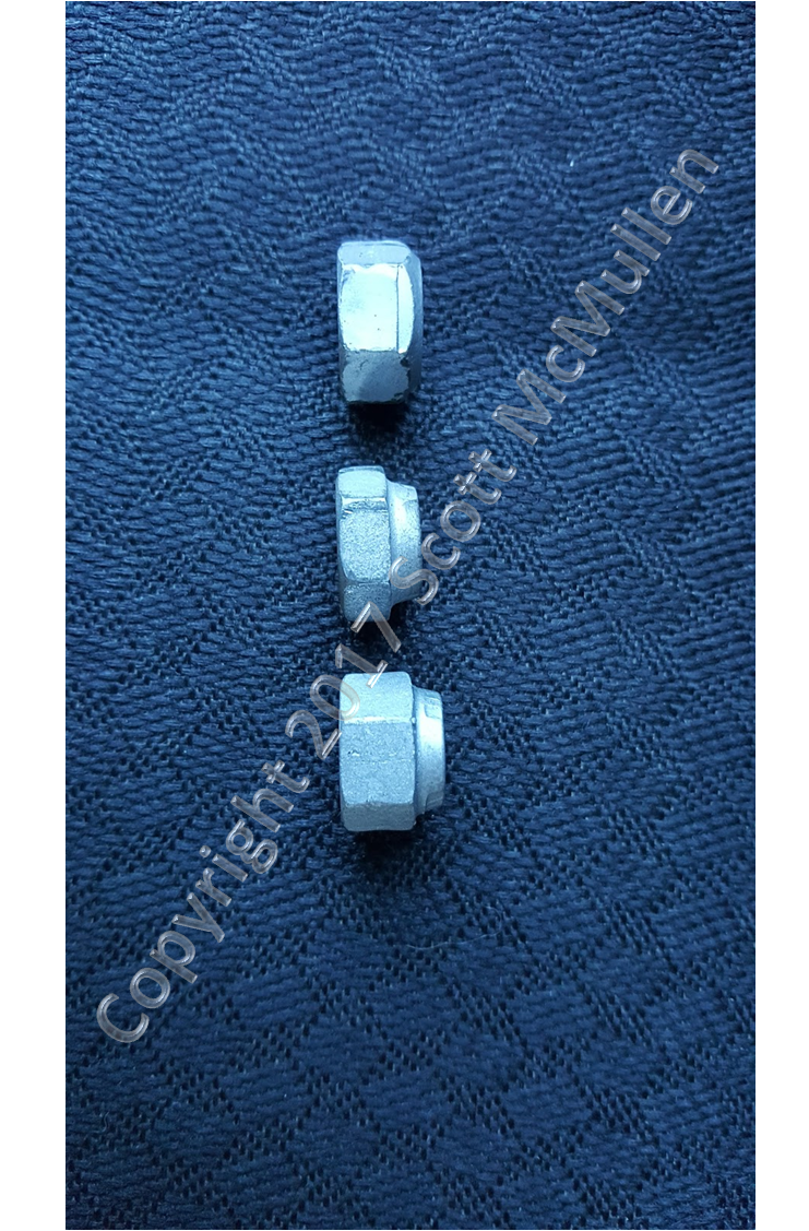
So after finishing up all of these nuts, I noticed that there are apparently 3 different versions of this 34445 nut.   One version has 6 raised dots (one on top of the nut at each shoulder designates grade 8, see nut at left), 3 dots( designates grade 5, middle), and a version without any dots(designates grade 2, right). The one without any dots was used on all 8 front spindle to backing plates.  I've seen these mixed on differential to axle housing attachment.  The no dot variety is also used on the rear axle housing to backing plates.

According to the parts catalog, this is also used to hold the rear axle rubber bumper to the bracket that attaches to the differential housing - it's specified as a 34445-S. 

 Interestingly, the assembly manual calls for a 34420-S8 or 55674-S8.  From Left to right below, 34445, 34420, and 55674.  Note that the 34420 (middle) came off of a 4F4 differential housing with 4F5 retainer and the 55764 came off of a  4E4 differential housing with 4D22 retainer.  So from sometime after May 4th 1964 (4E4) and sometime after June 5th, 1964 (4F5) two different nuts were used to attached the rubber bumper to the pinion snubber bracket.  The manual states that these two nuts were both an allowed fastener for this purpose.  All three of these are jamb nuts.


The nuts on the front spindles are identified simply as 34445 in the assembly manual, but as 34445-S in the January 1965 issue of the 1965 Ford Car Parts and Accessories Catalog.  The "-S" designation supposedly specifies the finish as "plain" but having pulled many of these off the car, it seems to mean either bare steel with cosmoline, dark phosphate and oil, clear zinc - so basically it seems that anything goes when comes to the finish.  It just seems that the assembly was done with the type of fastener that was in the bin at that stations on the line during that period of production.

So this may seem like an excessive amount of time spent on this, but the real reason for doing so is the value in being able to date and authenticate cars as this type of information is accumulated and documented. It's little things like the finish on certain nuts and bolts that can help to pinpoint time frames of when cars were assembled or whether they were built entirely, partially, or not built on the assembly line at all.  It's the accumulation of this and other data, and corroborating that evidence with a group of cars of the same time period coupled with hard documentation of other aspects (delivery time, purchase date, etc.) that allow us to piece the story together about a certain car or group of cars. 

So, why does it matter that some 34445 nuts are cadmium, other bare steel, others zinc.  Well it all has to do originally with the durability that Ford wanted (i.e. rust resistance).  Cadmium is used much less today and is a more costly process than say zinc chromates, but Ford may have decided that the rear axle nuts were going to see more splashing coming from the front tires that would be soaking these parts more than those on the front.  Maybe as production got more heated, they just started using whatever 34445 nuts that were on hand or maybe they simply had different parts in the bins for the front suspension assembly area on the line than those at the rear.  There is no way to be sure (yet!), but what we can be sure of is that this car had Cadmium plated 34445-S7 nuts used on the rear axle and zinc plated 34445 nuts used on the front.  So now, we can take that info and use it to compare and date other cars of the same period - and maybe a bigger story that we aren't even aware of yet will become clearer.


Wednesday, January 4, 2017

Details


 Made quite a bit of progress on parts over the last few weeks.  Including some before and after pictures.  Rear brake hose before,

Rear brake hose retainer to body bracket, note the"P", which is barely visible when installed.  

 Extension that attaches to the rear axle housing.  Note :"W" logo on the before pic.  Also, note how the original plating tended to be heavier around the edges, just like it came out after reconditioning and re-plating below.

This shows original paint daub on the rear brake hose...

On the other side there was a bunch of orange paint smeared along the length of the hose.  Never seen this before.
And here is the complete reconditioned hose assembly, no paint daubs added yet.
 Here is the backside of the brake hose to body bracket.  Looks like raw steel plate with cosmoline originally.

Here's where the bracket was attached behind the rear seat in the kick-up area in front of the axle...note that the underside of the car was painted black before this was installed.  Also, note how crudely the holes were drilled that attached the bracket to the body.  On every K code I've seen this bracket is welded in place, but on this car, the holes were drilled during the process of fitting the exhaust system on the car.  This bracket had to be located so that the brake hose would not interfere with the exhaust driver side pipe in the newly fabricated dual exhaust system.  In fact, you can see that the holes on the floor pan were drilled before the inner reinforcing plate was installed - you can see the reinforcing plate the enlarged holes in the floor pan.
Here is a view from the inside of the car showing the two bolts on the right that held the bracket in place.  To the left of those bolts are the two cadmium finished bolts that held the driver side exhaust bracket in place.  Later cars used a special bracket that had both bolts attached instead of two separate ones.  You can tell that there was never a bracket here.
These bolts will be reused as is, just cleaned up.  Again preserving as it was when the car was assembled the first time.

Here are the lower control arm to body bolts, lock washers, and nuts.  Also the original rear leaf spring forward attaching washers.
 Lower control arm fasteners after cleaning and re-plating.  Turned out awesome.  Note head markings, these are not reproduced.


Another cool part, these  are the before and after pictures of the front stabilizer to lower control arm extensions.  These are the sleeves with "FM" stamped into them, presumably for "Ford Motor" company.   Prevailing belief is that these sleeves were natural steel with phosphate/oil finish and that the bolts were also phosphate and oil with a blank head.  On this car, the bolts were marked "rockford" on the head, and the sleeves were clear/blues zinc.  The refinished parts turned out true to the original.

 Note how the original rubber insulators were marked with blue paint...have seen this on other early Hipo's.


Restored upper fender attaching bolts.

 Rear wheel cylinder with original paint daubs.  Both left and right rears were marked with orange and white...

...whereas the fronts were marked with black and orange.  This is totally different than the makings seen on other restored K codes.  These original markings will be preserved.

 Restored original motor mounts.  The finish turned out even better than i had hoped.  there was a blue spray painted spot on the drivers side mount that over sprayed on the lower cross-member that will be recreated at assembly time.

Rear shock to axle plate with original paint daub.
 After  restoration.

 Transverse muffler stamping.  Only 5-64 stamped dual exhaust transverse muffler I have ever seen.  Most NOS units are stamped 10-64.

Markings on front spindle.


 Orange paint daubs were used to locate the outer parking brake brackets.  There were many places on the car where orange paint was used for identification of parts specific to the K code.  Why these were marked is unclear since they are identical to non-hipo mustangs of the production period.  It may be that these too were fitted in place as part of the dual exhaust fitting process, as they determine the amount of parking brake cable held in place between the frame rails.
 Oddly, the inner parking brake cable brackets were painted black while the outers were natural steel.

 The original Ford assembly team scraped off the fresh under coating where the outer parking brake cable brackets would mount.  Note orange paint underneath.

Although you can't tell from the picture, some of this is rust dust that came out when the forward leaf spring bolts were removed.  The rest is orange paint.

These wires on the parking brake cables were a 64 1/2 Dearborn tool for keeping the cable out of the way during chassis assembly.


 Unbelievably, all of the original 64 1/2 dual exhaust brackets were still on the car.  The goofy spot weld on the upper left bracket was used on the installation of new resonators installed by the owner prior to me (I have the receipt).  These will all be refurbished and reused - possibly the first set of Mustang dual exhaust hangers, used during the hand-fitting of the new exhaust system to the car.


Thursday, September 22, 2016

Suspension

The uni-body is done with paint and is back home.  Next step is to make the car a "roller" again so that we can move it around and install then engine. Once the drive train is installed we'll send it back to the shop for final panel fit and hood install.  We've been stuck a little here while the suspension parts were getting restored.  Falling behind on the getting the engine assembled too, just too many other things going on

.  Should be back on schedule again in a couple of weeks.  Front suspension is done with restoration, and looks amazing. Brake backing plates just got finished an are ready for paint.  The really amazing thing is that all of these parts have matching numbers, more on that in a later post.
Finishing up restoring/plating original hardware. I hung the coil springs and dipped.  Was amazing how this accurately recreated the look of the paint on the springs originally
 The pattern of drips and coverage were true to the first time these were dipped back in 1964.  Some pics of the restored front suspension and steering linkage.

Background History

There are just a dozen or so of these 64 1/2 K code convertibles known to exist.  Of those, this is the only documented example that left the factory with an automatic choke and hand-fitted dual exhaust system, measures taken by Ford in order to get the car into dealer showrooms by the all important July 4th sales weekend in 1964.   High performance mustangs were originally to be available by June 1st 1964, but production delays would keep the K codes from entering regular production until the end of June - too late for arrival at dealers by July 4th, which fell on Saturday.  With this realization in mid June, Ford quickly made plans to assemble a few cars using existing parts from other high performance car lines already in production, namely the Fairlane. This car and perhaps a few others were quickly "show car prepared" and fitted with Cobra engine bay dress-up kits in time for them to arrive at select dealerships by July 1st.  There they would be shared with other dealerships in the sales district to entice buyers to order the new High Performance Mustangs.

I was able to recover some of the original factory documents and was able to interview several of the owners.
I'll be elaborating more on how the original owner acquired this car along with information from the dealership that originally sold the car in the coming weeks.

Thursday, July 28, 2016

Choke

Now that we're in the paint phase with the engine compartment, the whole automatic choke question has to be dealt with.  Bill and Bobby (1st and 2nd owners, respectively) both have stated vehemently that the car had an automatic choke (and no choke pull inside the car) when they each purchased the car.  In fact, the way that the "L" bracket is welded between the side of the cowl area to the dash, the holes for the choke pull bracket can't be mounted where it is supposed to go - the mounting holes in the bracket are blocked off by the holes in the bottom of the dash, due to misalignment - the tab on the choke bracket and the mounting screw won't fit through the holes.  That said, the car did have a manual choke when I acquired it, and Jay stated that as he and his son recalled, it had the manual choke cable when he painted the car in 1980.  Jay's recollection is that it was also there in 1973 when he first acquired the car.  The choke cable on the car when I bought it was only 46" long and the exterior covering was thinner and lacks the white line I have seen on other originals of the production period for this car (Fairlane was 58" long vs. the normal Mustang HiPo length of 63").  When I acquired the car, the pull was mounted in the "D" hole under the dash and the cable was routed in front of the fresh air vent inlet housing under the dash, rather than behind the fresh air vent as it was supposed to be.

The hole in the firewall is very crudely made, it was apparently drilled through first, then punched through with a rod from the firewall side, which splayed out the metal on the interior side of the firewall.  The metal that remained around the hole was then pounded flat against the firewall.  The area around the hole is dented by about a half inch towards the drivers side by hammering of the punch through the firewall and/or the prying action of the metal rod.

So the question is, "when was this hole made?"  Was this done at the factory or during the time between 1970 (when Bobby bought it with an automatic choke) and 1973 (when Jay bought it with a manual choke).  One wouldn't expect such a crudely made hole to be done as part of normal assembly procedures, but there are several other holes in the area around the dual exhaust that were all hand-cut, some very crudely.  So it's entirely possible, that the existing hole in the firewall was made with the intent of installing a manual choke later in the assembly process.  But, based upon the way that the hole was made and plugged it is very unlikely that this was a factory made hole.

One factor, is that it looks like the hole was made with the firewall pad in place.  The "chad" that originally covered the hole in the firewall pad was still hanging off the hole and will be reused with the original firewall pad in the restoration.

The other factor is that the assembly instructions called for any penetration of the firewall to be sprayed with sealer after the items penetrating the firewall were installed as one of the last steps before leaving the factory.  the sealer is often sprayed haphazardly, this is no exception.  There is sealer over-spray in the area where the cable goes through the firewall.  The plug of caulk that was used to seal this hole was applied over the spray on sealer, indicating that the hole was most likely made and caulked after leaving the factory.

With all of the evidence some restorers would go ahead and weld the hole closed.  In this case, however,  I am not going to do that.  I learned over the years that the best approach is one that leaves the most original evidence, so that if more info comes to light in the future,  we still have the ability to again review the original evidence against the new information.

This proved especially true of the lowest VIN coupe, 5F07U100002, that i sought out and bought in the 1990s, and subsequently sold to Bob Fria.  Had I chosen to restore that car using the prevailing knowledge at that time, much of what we learned about pre-production Mustangs would have been lost.

So I'm staying true to the statement in my introductory post, that this is a "minimalist restoration".  Therefore, the existing hole will be covered with body sealer that could be removed in the future without destroying historical evidence.  This is consistent with what the factory would have done if such a hole had been made at the factory and not used.

Just one more comment on what i mean by "minimalist restoration".  We are still doing a complete, down to bare metal, rotisserie restoration.  However, we have preserved every existing original marking and part that we could, and we documented in photos and accurately recreated those that could not be preserved without compromising the structural integrity of the car, its appearance, or durability of the restoration.

Thursday, July 21, 2016

Paint

Paint
The car is in the paint shop now.   I took samples from various areas over the car to determine what was on it and the order of application so that we could recreate the original colors and sequence of application accurately.  The colors of the new primers and paint were painstakingly matched to these colors.  The entire underside of the unibody, firewall, and aprons were originally painted with a very hard and glossy coat of black paint/primer, but not on the exterior of the core support (the factory markings are being preserved in their original state).  There was no red oxide under the body or on the exterior of the car, only in the trunk and interior of the car.  The exterior body panels, and the exterior of the core support and aprons were all shot with gray primer as it was originally. Put lots of effort into doing the procedures in the same order as the factory.  Also in recreating the original factory skid mounting points and overspray even in places that most folks will never see once the car is put back together.