Monday, December 17, 2018

Brake and Fuel Lines


Finally got to finish install of all the brake and fuel lines.  I had already put the long brake and fuel lines under the car many months ago, but go held up by the rear axle install and work buttoning up the engine.  Once the axle housing was installed with axles/backing plates and such I could get the brake lines installed.

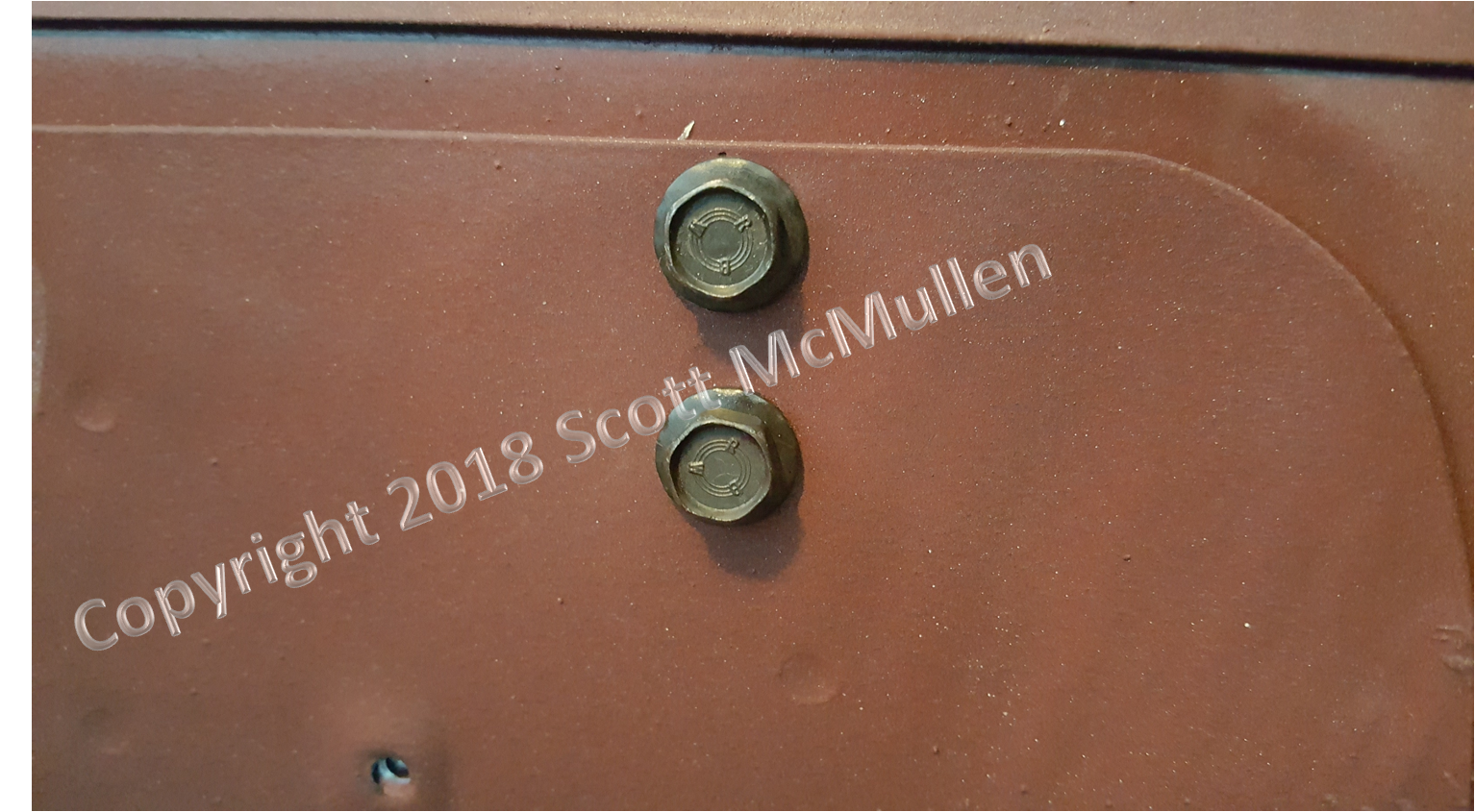
The next big thing remaining was the bracket that holds the flexible brake hose from the axle housing to the hard brake line on the body.  On all other K code cars of this period, this bracket is welded on to the body.  On this car it was held on by two screws with lock nuts.  When I took the bracket off it had been painted, but the surface against the body, was unpainted and had traces of cosmoline.  So I went about digging out a can of cosmoline I'd gotten back in the early 1990s when I had the 5F07U100002 and my July 13th D code convertible that I was restoring.  Amazingly, I had never used any of the contents and it actually sprayed great.  So I coated the bracket and let it cure for well over a week.  Looks great with the runs and drips, just like it did originally.

The original flexible brake line was is great shape and I was able to restore it and replate the fittings.  I recreated the paint markings exactly as they appeared before restoration.  Interestingly, the orange paint is not very visible once installed - obviously a mark to identify the part during selection prior to install.

The bolts that hold the bracket to the body were in good shape once I got the black paint off of them so I didn't replate them.  They even still had red paint marker in the threads from when they were first installed at the factory.  I also found some of this red paint stick paint on the back of the bracket, so I'm guessing that a red paint stick was used to mark the location where it needed to go and then the holes were drilled.  I recreated these before re attaching the bracket.

I also finished all of the lines in the engine compartment.  Getting the bends through the shock towers and into the wheel wells aligned with the 64 1/2 flexible brake line holding bracket was a very tedious and time consuming process.  The bend here is not correct, and there was still too much bend inside the engine compartment at this point...many hours of labor to get these right.  All original screws were used and the clips were replated as original along with using the original restored and replated junction block.

The screw on the left is what it provided by AMK in their brake line hardware kit.  Originals on the right were replated.


Also restored the original C4ZF-A fuel level sending unit.  Cleaned out the windings, reset the pickup and tested the resistance at Empty, Full, and everything in between.  Very pleased with the way it came out.  Note that I used a NOS fuel sock that is identical to the original, but in much better shape.  Here's a link to the first YouTube video in the series (there are 5 videos in the series) where I restore this sending unit.https://www.youtube.com/watch?v=Q__Kr855zhw

I then installed the sending unit and connected it as it was originally.  Really happy with the plating on the sending unit, just as it should be.  You can see the Ford script logo and engineering number.


Lastly, the axle vent hose was installed.  Original clamp and vent fitting, were used with an NOS vent hose, and body clamp.  All original bolts were replated and used.  Note that the axle brake hose metal bracket does not have the stepped bend as in later versions used after this in production.


Thursday, November 29, 2018

Rear Bumper


Finished installing the rear bumper and bumper guards.  Hardware for the guards and bumper is all the original, replated as original.  This is a tricky area, because again the assembly manuals are for later dated revisions.  These fasteners were restored as they were for the June 64 time period of manufacture.  The hardware was also a little different than what was pointed out in the manuals, but documented as the same fore several other cars of this period.

The bumper bolts themselves were different that what was provided by AMK.  I didn't like that the heads were not flush with surface of the bumper  and that they were just plain different than what was originally there.  So it was several days of extra work, but I couldn't be happier with the restored hardware.  Note that the bolt, nut, and washer on the left is what came from AMK, the rest are the originals form off the car.

After restoration...the heads of the original bolts have a much tighter radius on the outer edges and the square area that fits into the bumper is smaller...both of which allow these to fit flush to the bumper surface.  Removal of nicks and dents from the stainless steel caps on each bolt was extremely tedious...but they look better now than the new AMK bolts.

Trunk

Since my last post have finished assembly of the trunk area.  I ended up inspecting and cleaning the trunk harness.  It is amazing to me how well this survived over 54 years.  Most people (including me) would send the harness out to have the woven covering replaced.  In this case, it was in nice shape and you just can't get the covering to look exactly like it did originally after having it re-webbed.  Note the two colors that are used...Dark bluish-green and grayish-tan.   The string is impregnated with a waxy substance, replacement string is not, in my experience. 

I also finished the rest of the trunk interior.  Here are some shots. 


Discovered yet another oddity for the 64 1/2 cars of this era - the bumper brackets are held to the body of the car by gold cadmium bolts, along with a cadmium lock washer and a clear zinc plated conical washer.  This is different form the phos and oil bolt and the zinc dichromate conical washer called out by the assembly manual. AMK provides a longer bolt and a larger conical washer, consistent with the assembly manual.  I have documented 3 other cars (with pictures) of this June 64 period that used the setup on this car.


Wednesday, October 10, 2018

Intake Manifold

Intake manifold installed, exhaust manifolds installed engine painted and test fitting valve covers, carburetor, and air cleaner assembly.

But before installing, I added back the baffles on the underside of the intake.  Interestingly, in addition to the center baffle that is on all intakes, this also had the baffle at the back that was installed for intakes with a road draft tube -even though this intake was not machined for the road draft tube
(No hole at the rear).  This was presumably done because some non-hipo 289s got the road draft tube and front cover mounted oil fill tube, and it was easier to just install the rear baffle on all intakes rather than risk having one that was machined for the road draft getting released without the baffle, which would possibly result in oil leaking out of the road draft tube and the rear of the engine.


 Shown without rivets yet installed.

Another weird thing that cost a ton of time an effort was the plug for the rear lifter oil supply galleries, located at the rear of the lifter valley. 


This is supposed to have a 3/4" plug, but on this engine it took several cycles of trial and error before I finally found the right sized plug.  I've seen where other people have used the 3/4" plug, but had to stake it in place.  This is just another one of those weird things that is different about this transition period of 289 production - other 289s I've worked on the 3/4" plug worked just fine without staking.  Because the hole is slightly irregular, measuring the diameter gave varying results so I tried 3/4 too small, 7/8 too big , 51/64 too small, and finally 53/64" plugs. Of course, as luck would have it, the one that fit was discontinued and I ended up having to pay for the entire remaining box in the US, plus shipping to a local auto parts store in order to get just one plug - but I got it and it fit! 

Shot of an original plug on another 289 I have in the shop.

 Plug ready for driving in with a socket.

 I taped off the entire valley with plastic in case there were any shards of metal when I drove the plug in and I'm glad that I did, with the hole being slightly irregular.


 Plug driven in to the proper depth.


Tuesday, October 9, 2018

Installing Heads

Original 289 HiPo heads, as indicated by the 289 with two dots above.  White paint mark in the center is an original inspection mark.  These were cleaned and assembled with NOS and original Ford script valves that were "re-hard chromed" as they were originally, but now to suit guide clearance.  Retainers are also original 289 HiPO.  I chose not to install bronze guides, everything is as it was when original.  Some might push for bronze guides, like I have done on other cars, but these Hipo heads from this period are so rare that I would not want to do anything to modify them.  On top of that the bronze guides are really not necessary, given the amount of mileage this car is likely to get, or get some fuel additive that does the work that leaded gas supposedly did back in the 60s.  I know plenty of guys that have original un-restored heads and they are working just fine after more than 50 years of service.

The biggest issue I had with installing these heads were the rocker arms.  First, it was a pain to find a complete set of NOS rocker arms.  Second, once I was able to cobble together a complete set, as I went through checking rocker geometry, I found several that weren't landing in the middle of the valve tip.  So I had to GO AND FIND MORE!!!  Finally, I was able to get everything just right with initial cold lash set (I'll adjust "final" hot lash after initial run in).  This was necessary because with these vintage rocker arms there are slight variations in the rocker arms (like the contact area of the tip not being symmetric or level with the valve tip).  Anyways, it took several weeks to finally get all the parts, get everything installed and geometry set. Here what I got finally, where pattern pretty well centered from inside to outside of head on the valve tip.  Just can't get any better than this with old school solid lifters and solid rocker arms (non-roller type).
Here's an example of one of the rocker arms while going through the process of checking geometry.
Setting cold lash.


Axle Housing Install

I realized that the leaf spring pins that the spring shop used to assemble the restored spring leafs were too short a while back and I knew they would have to be replaced later.  The head of the pin acts as a rough guide for the axle housing placement on the leaf spring assembly.  Fortunately, these pins are available and I was able to replace them before installing the axle housing.

On the left is the correct bolt, on the right is what the spring shop installed initially after re-arcing the individual leafs to original specifications.  Most shops won't have these correct longer head bolts.

And finally there it is installed.
I made sure that the bolt was precisely centered in the middle of the leaf spring mounting plate, as well as the upper head of the bolt in the axle housing mounting pad. The yellow mark is an inspection mark, duplicated exactly as it was shaped and applied originally.  There is a pic of the plates before restoration in an earlier post.

And finally the install of the axles, after installing new seals. Care has to be taken when putting these in so that the splines don't damage the seal.  Note the original orange mark on the shaft.  These were cleaned and new bearings in stalled.  The original brake backing plates were restored so that the flat contact points where the brake pads rest are nice and smooth.  Not everyone does this, but I can tell you if the wear grooves in the plates are left unfilled, the brake operation will be impacted.  The other thing I see are restorers gobbing powder coating on these inside of the plates...this will screw up operation as well.
Really happy with the  way this rear axle components came out after restoration and install.  Still more details to add, but the immediate objective is to get everything under the car installed while up on the RV jacks.  Once off the jacks, the motor, trans and driveshaft are going in.

Monday, October 8, 2018

Oil Pump and Pan

 Finally posting pics from several months ago.  This was installing new Ford oil pump, new driveshaft, cleaned and polished bolts.
 Oil pan fasteners before cleaning...nearly forgot that I needed to do these, since they get painted with the engine.
 Note original counterweight forward of the first main bearing.  New Ford oil pump and original pickup was disassembled cleaned and reassembled.
 Pan attaching hardware after cleaning...note different head stampings.

 The pan is on, finally!
 New bronze pilot bushing in the crank.
 Rare to see the Ford script on an oil pan of this vintage...this is right after media blasting.  The pan appears to be stamped June 11...but hard to see.
 One final note.  I noticed this small mark near the Ford script stamp on the crank before I put the pan on.  Looks like a Brinnell hardness test mark.  I've seen earlier cranks that have a highly polished area where the cranks was supposedly inspected visually.  This mark is different than what is on the flywheel, it is a single conical indent.  Cool stuff - and yes that is original orange paint on the piston rod, they were just cleaned not media blasted.

Wednesday, June 13, 2018

Timing set and Front cover


This is the starting point for installing the front cover.  The cam retainer for the 64 1/2 HiPo 289 of this period was the rare "two level" with counter sunk screws.

Next come the cam "C" spacer.  I managed to find an NOS unit to replace the original.  I was also able to find NOS cam and crank sprockets.


The front counter weight attaches to the crank sprocket with a roll pin that has to be driven in to just the right level so as not to interfere with the beveled edge that snugs up to the radius on the front bearing journal.  The roll pin is just there to ensure the proper alignment of the counterweight with the rotating assembly as balanced.  When the time comes the flywheel will be installed in the orientation it was in during balancing as well, but that's a ways off yet. 
 
And here it is assembled

With that, the rest of the timing set can be installed.
And now the Front cover is installed.  Incidentally, I've recorded all of the actual torque for each bolt in the engine, including the front cover bolts.  Note the original C5OE damper dated L3.  Of the original cars of the period all dampers were dated L3 or A5.  This one is in great shape.  It was restored with new rubber, and still shows the lines on the exterior surface that go all the way around.  Most dampers have had rust or dents.